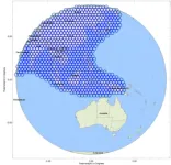
First, the payload requirements and problems faced by traditional multi-beam antenna are described. The user beam of the VHTS payload system mainly uses Ka-band multi-beam antenna for a large range of area coverage, and the number of beams in the coverage area is not less than 500, usually using 7-color frequency reuse scheme(Fig. 2). At present, the spaceborne multi-beam antenna technology applied to high-throughput communication satellites is usually divided into multi-aperture multi-beam antenna and passive multi-feed multi-beam antenna. Multi-aperture multi-beam antenna is usually composed of 3 to 4 reflector antennas, when facing the demand of super-large coverage, the edge beam gain is rapidly reduced, the beam is deformed, and the sidelobe is increased. The passive multi-feed multi-beam antenna is based on the waveguide beam forming system, which usually consists of 2 reflector antennas, and the edge beam in a large coverage area can be compensated by optimizing the amplitude and phase excitation coefficients of multiple feeds. The number of feeds of typical products of this technology is usually 2.5 to 4 times the number of beams. For the demand of more than 500 beams, the number of feeds is to huge and complicated for satellite engineering applications. Additionally, active multi-feed multi-beam antennas are widely used in mobile communication satellites. This type of multi-beam antenna usually adopts a large mesh reflector combined with multi-feed array which have been put forward to achieve primary sub-beam defocusing, thereby achieving high-level over-lap of all sub-beams. The gain and sidelobe of the beams are optimized through full array synthesis. The payload system basically adopts 12-color frequency reuse, and the C/I is about 12 dB, which cannot meet the requirements of 7-color frequency reuse and C/I≥15 dB for VHTS. Meanwhile, there are too many feeds to form a single beam, and the beam forming network is too complicated when facing the huge number of beams.
Figure 2 VHTS coverage for Asia-Pacific region(976 0.25°beams)
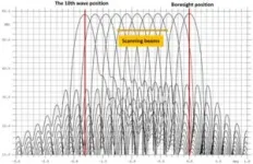
Then, the scholars describe the design theory and optimization method of active multi-beam antenna and propose a new design method of active multi-beam antenna based on multi-target cooperation and multi-feed amplitude and phase weighted optimization algorithms. The method takes the amplitude and phase excitation coefficient of feeds as optimization variables, establishes objective functions based on the number of synthetic feeds, the gain of synthetic beams and different C/I, and obtains a balanced optimal solution that meets the performance requirements. In order to solve the problem that it is difficult to obtain the optimal solution for complex nonlinear optimization caused by multiple objective functions solving the target coupling and the problem that the optimization speed is too slow, this paper proposes the surrogate model of convolutional self-encoder based on artificial intelligence (AI) technology for the multi-objective optimization solution, which efficiently completes the search for the optimal beam excitation coefficient. The method concludes 8 steps. Step 1: The GRASP model is carried out for the multi-beam antenna. GRASP is used to analyze the main lobe gain, sidelobe level, and beam direction results of the sub-beam pattern of each feed. Step 2: Python-GRASP is adopted to co-simulate the typical beam position parameters (ucenterMR, vcenterMR) of the synthesized beam, the number L of feeds involved in the synthesis, the amplitude/phase weights aRi and pRi of each feed, and the performance of the synthesized beam under the disturbance of parameters. Step 3: The convolutional auto-encoder proxy model is constructed experimentally, the parameters in the model are determined, and the convolutional autoencoder is trained. Step 4: Determine whether the model fits according to the test set and the surrogate model prediction results. If yes, save the above nonlinear related parameters; otherwise, repeat Step 3. Step 5: Initialize the max-min algorithm, debug the parameters in the max-min algorithm, design the optimization objective function according to the antenna optimization index, and load the trained convolutional autoencoder proxy model. Step 6: Calculate the residual value (main lobe gain, sidelobe level, and beam direction) in the 2-dimensional sampling point (u, v) of the spatial electric field corresponding to the optimal solution in the max-min algorithm, and then the algorithm performs iterative optimization. Step 7: Determine whether the residual (main lobe gain, sidelobe level, and beam pointing) values in the 2-dimensional sampling point (u, v) of the spatial electric field corresponding to the optimal solution meet the set optimization index. If the optimization index is met, the algorithm stops the iteration; otherwise, it returns to Step 6. Step 8: Put the number L of feeds and the corresponding optimal solution of amplitude/phase weights into GRASP to calculate and verify the accuracy of the optimization results of this scheme. The active multi-beam antenna designed by the proposed method can make up for the scanning loss very well (Fig. 8).
Fig. 8. Pattern of beams at different wave positions formed by an active multi-beam antenna.
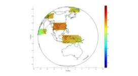
Finally, the design and simulation of active multi-beam antennas are carried out based on the technical requirements of VHTS in Table 1. The aperture and focal length of the receiving antenna are 3.2 m and 5.8 m respectively, and the aperture and focal length of the transmitting antenna are 5.0 m and 9.0 m respectively. Under the coverage of nearly a thousand beams, the antenna achieves ultra-high gain of more than 50dBi (Fig. 14) and ultra-high C/I of more than 18dB (Fig. 15), supporting the communication capacity to achieve Tbps level.
Figure 14 Transmitting beam gain pattern (partial area)
Figure 15 Transmitting beam C/I (partial area
END


